POWERFUL TOOL.... The DYNA2D Finite Element Code by
Livermore Software
Technology Corp is a very powerful 2-D tool for calculating
the dynamics of axisymmetric structures. DYNA2D was used to
calculate the resulting plastic deformations and loads for a 243
Win Winchester brass rifle cartridge case pressurized to 50,000
psi in 0.5 millisecond (ms) by a ramp pressure loading. After
loading, the pressure was removed in 0.1 ms and then the zero
pressure state was allowed to remain for another 0.1 ms. Each
calculation used the same geometry and pressure loading and only
the coefficient of friction between the cartridge case's wall and
the rifle chamber was changed. There is info on how could
actually measure a representative chamber pressure
here:![]() Recreational Software, Inc. Software &
Instrumentation Technology for the Shooting Sports.
Recreational Software, Inc. Software &
Instrumentation Technology for the Shooting Sports.
MATERIALS AND GEOMETRY.... Each calculation took about 5 hours on my old Pentium P-5 200 MHz computer. It took about 3 days to generate the mesh from the the photograph, scale it to the correct size, and adjust the mesh density to be finely divided at the points of interest and still have enough reasonable detail in the rest of the geometry. The brass case head and walls were 1/2 hard cartridge brass with a yield of 52 ksi and an ultimate of 62 ksi. The cartridge case's shoulder and neck were of annealed cartridge brass with a yield of 19 ksi and an ultimate of 51 ksi. The primer was annealed cartridge brass. The barrel material was 416 stainless steel and was fixed in the vertical direction for 1.25" simulating the thread where the barrel joins the rifle action. The bolt face was 4140 steel that was fixed in the axial direction at its lower surface. There was an ~0.002" radial clearance between the brass and the chamber. There was a 0.006" axial clearance between the brass case head and the bolt surface. This clearance was used to simulate the bolt lug deflection that occurs during firing. The firing pin was not included in the model merely to simplify mesh generation. I have the dimensions of the firing pin and plan to include it eventually.
This is a plot of the material properties of the Half-Hard
Cartridge Brass that was used in the calculations.
I have heard that the brass at the cartridge head is in the
Full-Hard condition on some measurements.
I plan to repeat a couple of the calculations with Full-Hard
Cartridge Brass and increase the pressure
to about 55,000 psi.
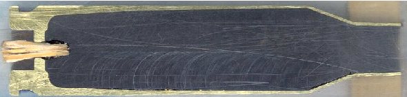
THE SECTIONED CASE.... Dick Hatfield
sectioned a 243 Win Winchester case with his milling machine and
scanned it so I could get the dimensions.
Many places have the outside dimensions of various calibers, but
this was the only way I could get the internal dimensions.
The wooden plug was used to keep the clear epoxy from running out
while he was molding the inside.
 243 Win Winchester brass. Barrel Dia =1.25" Bolt Face is fixed. The primer is a press fit. |
 Complete mesh detail. Radial clearance between brass and barrel of ~0.002" |
 Close up of the mesh detail at the brass case head and primer. Axisymmetric 2-D mesh with 1979 nodes, 1670 elements, 5 materials, and 4 sliding surfaces with friction. Gap of 0.006" from the bolt face to the brass case head. (simulates action and bolt lug stretching during firing). |
RESULTS FOR A RANGE OF FRICTION COEFFICIENTS.... In each calculation, only the friction coefficient was changed. The plastic strain, case thinning, and bolt face loads were calculated for seven different static friction coefficients. I have tried to identify the friction coefficients by the approximate surface conditions. Dick Hatfield has completed a Friction Coefficient Test to better quantify the friction coefficient with surface conditions and lubrication. The plots are in the order of decreasing friction coefficients. I have tried to identify the surface conditions that would give these friction coefficients, but extensive testing would be required to quantify these numbers and surface conditions accurately. Friction coefficients below u = ~0.1 are very difficult if not impossible to achieve unless a film of grease is trapped between the surfaces.
WHAT IS THE FRICTION COEFFICIENT?.... The friction coefficient is a dimensionless number and is the ratio of the force to cause sliding divided by the normal force the object applies to the sliding surface. Imagine a block of wood setting on a table. If the coefficient of friction between the block of wood and the table surface is u = 0.6, for example, then if you push down with a 10 pound force on the block of wood, it would take a 6 pound force parallel to the table's surface to make the block slide across the table.
 Contours of effective plastic strain after unloading from a peak pressure of 50,000 psi. |
 Contours of radial displacement after unloading from a peak pressure of 50,000 psi. |
 Curve a is the brass case load on bolt face Curve b is the primer load on the bolt face Curve c is the total load on the bolt face (a+b) |
|
|
Coefficient of friction u = 0.55 (Very rough chamber, rough reamer finish) Maximum plastic strain = 14.39% Radial thinning near the base = 0.006504" Maximum bolt load = 4435 lbs |
 |
 |
 |
|
|
Coefficient of friction u = 0.41 (Rough chamber finish, 320 grit finish) Maximum plastic strain = 13.42% Radial thinning near the base = 0.006238" Maximum bolt load = 4386 lbs
|
 |
 |
 |
|
|
Coefficient of friction u = 0.35 (Smooth chamber, 600 grit) Maximum plastic strain = 12.87% Radial thinning near the base = 0.006046" Maximum bolt load = 4639 lbs
|
 |
 |
 |
|
|
Coefficient of friction u = 0.25 (Smooth chamber, crocus cloth or smoother) Maximum plastic strain = 11.10% Radial thinning near the base = 0.006046" Maximum bolt load = 4477 lbs
|
 |
 |
 |
|
|
Coefficient of friction u = 0.19 (Polished chamber) Maximum plastic strain = 9.689% Radial thinning near the base = 0.004858" Maximum bolt load = 4565 lbs
|
 |
 |
 |
|
|
Coefficient of friction u = 0.11 (Probably not possible: Polished chamber, polished brass with grease) Maximum plastic strain = 7.923% Radial thinning near the base = 0.004481" Maximum bolt load = 4787 lbs
|
 |
 |
 Note the scale change: 0-8000 lbs |
|
|
Coefficient of friction u = 0.01 (Friction this low is not possible, but the calculation is interesting) Maximum plastic strain = 14.17% Radial case head expansion at the base = 0.009328" Maximum bolt load = 7665 lbs Note: This is nearly the maximum bolt face load that would occur if the case head were to completely separate after thinning. The case head separation load would be 8785 lbs, assuming no gas leak.
|
Summary Table with Estimated and
Measured Coefficients of Friction
See the Friction Test Results
| Estimated/Measured Coefficient of Friction (u) | Comments | Maximum
Plastic Strain (%) |
Cartridge Case Wall Radial Thinning (inch) | Maximum Bolt Face Load (lbs) |
| 0.55 | Very rough chamber, rough reamer finish with tool marks | 14.39 | 0.006054 | 4435 |
| 0.41/0.37 | Rough chamber finish, 320 grit finish (200 grit) | 13.42 | 0.006328 | 4386 |
| 0.35/0.29 | Smooth chamber, 600 grit | 12.87 | 0.006046 | 4639 |
| 0.25/0.27 | Smooth chamber, crocus cloth or smoother | 11.10 | 0.005415 | 4477 |
| 0.19/0.19 | Polished chamber Flitz | 9.69 | 0.004858 | 4565 |
| 0.11* | Probably not possible: Polished chamber, polished brass with grease | 7.92 | 0.004481 | 4787 |
| 0.01 | Friction this low is probably not physically possible and would be dangerous | 14.17 | 0.009328 (case head expansion that could cause the case head to rupture) | 7656 |
| 0.00 | If Case Head Separation (Hand calculation f = pressure * area) |
8785 |
* Note: I am not suggesting using lubricant on ammunition brass. I am merely trying to identify how this low of a friction coefficient might possibly be obtained.
DISCUSSION.... There have been many statements about the necessity of having a rough or "not too smooth" rifle chamber and for sure, not polished rifle chamber. Many of the statements go on to say that the friction between the cartridge brass and the rifle chamber prevent the load on the bolt face from being excessive. This series of calculations show, at least to me, that the bolt face load is not appreciably higher with a smooth or polished rifle chamber. What a rough or high friction rifle chamber does do is to stretch the brass on each firing if full length resizing is used. If only neck sizing is used, and the bolt closes with mild resistance, then only the deflections in the bolt lugs and the action stretching will, with a rough chamber, contribute to more brass case stretching but will be kept to a minimum.
POLISHED CHAMBER NOT ZERO FRICTION.... One of the misconceptions, I believe, is that many people perceive that polishing the rifle chamber leads to a friction coefficient of zero. That is not the case. Even when polished, the surfaces under high magnification look like raspy files and the imperfections of the mating surfaces lock up with each other and still exhibit friction forces. A polished rifle chamber does not lead to excessive bolt load forces.
THE BRASS STRETCHES.... At modern rifle gas pressures, the brass case stretches to let the case head rest on the bolt face. The tri-axial state of stress in the case wall will allow for but a few thousand pounds of axial force before the cast will undergo plastic flow. For the 243 Winchester caliber if the friction is great enough for the brass body to sticks to the chamber, plastic flow near the Full Hard case head will begin at axial force of about 3600 lb. If you experience case thinning near the case head on your brass, it can probably be reduced by polishing your rifle chamber.
THE BRASS THINS NEAR THE CASE HEAD.... With a rough finish on the rifle chamber, the brass case very early on is forced out against the chamber walls and is essentially locked in its axial position. Then as the pressure increases, the case wall is stretched near the case head till the axial load is supported by the bolt face.
WHAT IS EFFECTIVE STRESS?.... Here is some information on Effective Stress or often referred to as Von Mises Stress. In structures under load, the stress state is not a simple uniaxial state of stress but a more complex triaxial state of stress. Plastic deformations (also called plastic flow) will occur in a material when the effective stress, seff exceeds the uniaxial yield stress. Here is the equation for the effective stress when a triaxial state of stress exists and s1, s2, and s3 are the principal stresses in the three orthogonal directions. The effective strain is eeff.
seff = (2½/2) [(s1—s2)2 + (s2—s3)2 + (s3—s1)2]½
eeff = (2½/3) [(e1—e2)2 + (e2—e3)2 + (e3—e1)2]½
1. When all three orthogonal stresses are equal (hydrostatic stress state), the effective stress is zero. There is no yielding.
2. When s2
and s3
are zero, then the effective stress is the uniaxial stress. This is the stress condition of an axial pull test specimen.
Looking at the equation, one can see some interesting concepts. If there is no tension, but sufficient biaxial compression in the other two directions, then there could be axial yielding in extension in the third direction.
(This is like squeezing a cylinder of putty in your hand and having it squirt out each end).
WHEN YIELDING OCCURS.... One can visualize yielding as a cylinder in 3-D space. The axis of the cylinder is the line of the hydrostat. It is a line where
s1=
s2=
s3. When the triaxial stress state deviates from the hydrostat line
but stays within the cylinder, there is no yielding. When the triaxial stress state deviates from the hydrostat outside of the cylinder then yielding occurs.
NO YIELDING IN HYDROSTATIC COMPRESSION.... When a metal is in hydrostatic compression (immersed in a fluid and the pressure increased), there is no yielding, no matter how high the pressure. With a real material, micro voids would be closed and at extremely high pressures,
the crystal structure could be changed, such as converting carbon to a diamond. These pressures are beyond those normally considered in engineering
analysis of the strength of structures.
NO YIELDING IN HYDROSTATIC TENSION.... When a metal is in hydrostatic tension, in theory, there is no yielding. I can't think of any realistic way to apply extremely high hydrostatic tensions. The limiting point would be the bond strength of the atoms in the crystals.
Finally... The unsupported portion of the cartridge case heads are in a complicated triaxal stress state at each location and the FEA codes determine this for each
tiny element. The back-of-the-envelope p/a type calculations are of little value in
accurately predicting and understanding what is happening during loading such
structures where a triaxial state of stress exists.
|
Responses to Questions posted on the Go Go Varmint Go Message Forum
Posted by Hitman
I know the smoother the surface the less the coefficient of friction, but I have found that is is sometimes difficult to match the properties of materials with "real world" conditions. Despite what the actual numbers are, I think you have clearly shown that a polished chamber results in negligible impact on bolt thrust and a polished chamber likely will result in minimal brass flow.
Nice work!
At what point on the curves does the pin hit the primer?
What kind of a model did you use for the primer cup? Non-deformable?
The coefficient of friction appears to be a significant factor to the start time of case-head load. Would you give some possible reasons for that?
The total energy (force over time) on the bolt face is much greater for a smooth chamber. This implies that the forces are being exerted elsewhere with a rough chamber. What are the implications of this and how would it effect (increase or decrease) failure of the chamber/bolt system?
Thanks, |
FULL HARD BRASS.... There was a request to repeat the calculation with the brass head in the full hard condition. Since there are only two friction conditions, it was possible to compare more of the stress states in a reasonable space. The lower friction increases the bolt face load about 10%, but also reduces the thinning of the brass where case head separations occur. From my Reloading Page, I will restate one of my comments here: "Trying to use the weaker brass to lighten the load on the action and bolt face of a rifle by having the brass grip the chamber is analogous to using a car's radiator to protect the bumper in a front-end collision. A polished chamber minimizes case stretching, reduces case head separation, and increases case life."
| Comparison
of 243 Win cartridge brass with the case head in the full-hard
condition. The maximum chamber pressure was 55,000 psi. |
|
| Coefficient
of Friction m = 0.41 (Rough Chamber) |
Coefficient
of Friction m = 0.19 (Polished Chamber) |
 Maximum effective plastic strain of 10.36% (red color) View after pressure unloading. This is the region where thinning occurs that leads to case head separation. |
 Maximum effective plastic strain of 6.012% (within blue color) View after pressure unloading. |
 Contours of radial stress at the 55,000 psi peak pressure. |
 Contours of radial stress at the 55,000 psi peak pressure. |
 Contours of axial stress at the 55,000 psi peak pressure. The higher friction increases the axial stress. |
 Contours of axial stress at the 55,000 psi peak pressure. |
 Contours of hoop stress at the 55,000 psi peak pressure. |
 Contours of hoop stress at the 55,000 psi peak pressure. |
 Contours of maximum principal stress at the 55,000 psi peak pressure. The 71,880 psi stress is 87.5% of the true ultimate stress. |
 Contours of maximum principal stress at the 55,000 psi peak stress. The 68,550 psi stress is 83.4% of the true ultimate stress. |
 Contours of radial displacement. The case thins about 0.0025" at the red contour. |
 Contours of radial displacement. The case thins about 0.0019" at the green contour. |
 a = Axial force on the case head. b = Axial force on the primer. c = Total axial force on the bolt face. Maximum total force on the bolt face is 4,130 lb. Stretching the brass reduces the bolt face load by only 449 pounds. |
 a = Axial force on the case head. b = Axial force on the primer. c = Total axial force on the bolt face. Maximum total force on the bolt face is 4,579 lb. |
 Animated view of the displacements and contours of effective plastic strain. |
 Animated view of the displacements and contours of effective plastic strain. Note that the case head contacts the bolt face at a lower pressure with less friction. |
The material properties of full-hard cartridge
brass.
Note: At an 8% elongation, the True Ultimate stress is 82.17 ksi because of the reduction
in area.
| Material Name and Condition. | Density lb/in^3 |
Youngs Modulus msi |
Poisson's Ratio |
Yield Stress ksi |
Ultimate Stress ksi |
Elongation % |
Reduction in area % |
CTE per °F |
Yield Offset % |
| Cartridge Brass Cu.7 Zn.3 dead soft | 0.308 | 16.0 | 0.33 | 11.0 | 44.0 | 68.0 | - | 11.10 | 0.50 |
| Cartridge Brass Cu.7 Zn.3 annealed | 0.308 | 16.0 | 0.33 | 19.0 | 51.0 | 55.0 | - | 11.10 | 0.50 |
| Cartridge Brass Cu.7 Zn.3 1/4 hard | 0.308 | 16.0 | 0.33 | 40.0 | 54.0 | 43.0 | - | 11.10 | 0.50 |
| Cartridge Brass Cu.7 Zn.3 1/2 hard | 0.308 | 16.0 | 0.33 | 52.0 | 62.0 | 23.0 | - | 11.10 | 0.50 |
| Cartridge Brass Cu.7 Zn.3 H04 full hard | 0.308 | 16.0 | 0.33 | 63.0 | 76.0 | 8.0 | - | 11.10 | 0.50 |
| Cartridge Brass Cu.7 Zn.3 H06 ex hard | 0.308 | 16.0 | 0.33 | 65.0 | 86.0 | 5.0 | - | 11.10 | 0.50 |
DANGEROUS TO ANNEAL THE CASE HEAD.... I have done a Finite Element Analysis of the 243 Win brass case for the full hard condition and in the annealed condition, if someone were to inadvertently anneal the case head. Here is a view of the brass deformations after a standard load has been fired that developed 55,000 psi. The annealed case head would most likely rupture and vent gas into the action and destroy your rifle. The calculation didn't allow for actual rupture, but allowed for the brass to stretch. But, you can see the deformations just before the brass ruptures. Notice how much the primer pocket expands. The red dots show the original un-deformed outline. A normal case head in the full hard condition is shown for comparison.
 Full Hard 243 Win case head. View after a 55,000 pressure loading! This is a normal loading and a safe case head. |
|
 This view shows the plastic strain. There is very little plastic strain in the case head. |
|
Good Hunting... from Varmint Al
For the serious reader: How to Check Another Engineer's Calculation.![]()

|
|
||||
|
|
Last Updated: 01/21/2011
End of Page![]()